Description & Table of Contents of Tech Tips
Here at MPT Drives, we believe that our success is a satisfied customer. TechTips is designed to become a reference library for you to troubleshoot and solve the most common product questions. You'll find helpful tips on getting the most out of your investments. The information contained within our "Tech Tips" is for informational usage only. The information provided is based solely on our experience, it is not intended to replace or circumvent the user manuals supplied with our products.
- V-Belt Maintenance
- V-Belt Matching
- Proper Bearing Installation
- Saving Downtime
- Gearbox Selection
- Warner Electro module Clutches & Brakes
- How hot is too hot?
- Linear Positioning Accuracy
- Roller Chain Sprockets With Extended Pitch Chain
- McGill Nomenclature
- Torque Overload Release Couplings
- The proper method of loading a Shaft Coupling
- Sizing or Re-Sizing V-Belt Drives
- Diagnosis of problems in Warner Electric Clutches and Brakes
- Torque Limiters- Mechanical Vs. Electronic Devices
- What is Horsepower? What is Torque?
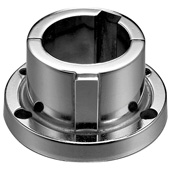
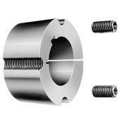
- Taper Bushing Systems NEW!
- More Coming Soon!
Diagnosis of problems in Warner Electric Clutches and Brakes
Warner Electric Electromagnetic Clutches and Brakes are basically simple, very reliable devices. Problems with a unit that is not functioning are usually easy to diagnose with a few simple tools and a little knowledge. The only tools needed to diagnose most problems are a Screwdriver and a Volt/Ohmmeter.
Only three things are needed for an Electromagnetic Clutch or Brake to function: Proper voltage, usually 90 Volts DC, Proper resistance in the electromagnetic coil, usually about 100-1500 OHMS and a Proper air gap between the armature and magnet or armature and rotor, usually about 1/32"
The most common problem with a nonfunctioning new unit is too large of an air gap. A used unit that has been functioning usually does not have this problem, if the gap has not been disturbed. Once the gap is properly set, the auto gap feature maintains the gap for the life of the unit. The gap is set, by pressing the armature manually into the magnet or rotor. The armature will then pop back to the proper setting, about 1/32" A unit that is functioning will have visible motion and sometimes an audible click when the magnet pulls the armature and closes this air gap. The air gap can be adjusted by hand on open units, but is a slightly more complicated procedure on Unimodules and Electromodules. These units must be adjusted with a flat blade screwdriver, inserted through the outer housing, and through an oblong slot in the fan. This is best done after consulting an instruction manual.
If you do not have access to a Volt/ Ohmmeter you can perform a simple test for the presence of magnetism. With the motor power turned off and, the power to the clutch or brake turned on, place an unmagnetised steel screwdriver near the magnet. If the screwdriver is drawn to the magnet, magnetism is present and voltage or resistance problems can normally be ruled out. The air gap is the likely suspect. If there is no magnetism, the voltage and resistance must be checked.
If you have a Volt/Ohmmeter, set it to the 90 Volts DC scale and test for voltage at the coil terminals. If there is no voltage, check for voltage at the power supply output terminals. If there is voltage at the output terminals, but none at the coil terminals, there is a problem with the wiring or switching in between the power supply and magnet. If there is no voltage at the power supply output, check for voltage at the input. If there is voltage at the input but none at the output, make sure any voltage adjustment pots are turned up, and the fuse is not blown. No voltage at the input indicates a problem with the wiring, fuses or switching on the input side. If a blown fuse is replaced, and continues to blow, check the coil resistance.
If there is voltage at the coil terminals, but the unit fails to function, disconnect power and remove the wiring from the coil terminals. Set the Volt/Ohmmeter to the resistance scale. Test the coil resistance by connecting the Volt/Ohmmeter probes across the coil terminals. The specifications for proper resistance can be found in the Warner Electric catalog or, can be obtained by calling MPT Drives. (800.473.7433) Lacking the proper resistance specification, you can use an approximate value of 280-300 ohms. Usually when a coil fails, it will measure either zero, indicating a shorted winding or, infinite, indicating an open winding. Zero, or very low resistance will blow fuses in the power supply. A coil with out of spec resistance needs to be replaced.
One last thing, most mechanic types are used to seeing automotive style brakes. In an automotive brake, metal-to-metal contact is an indication of a problem. Since Warner Electric clutches and brakes are electromagnetic, metal-to-metal contact is essential, and is not a cause for replacement. Do not reface a magnet or armature that looks worn. If it has worn beyond serviceable limits the components need to be replaced.
If you have checked and verified the presence of Proper Voltage, Resistance and Air gap, the unit closes the air gap when the power is on but still fails to run, check for a mechanical jam in the driven machinery. If all of these things are checked and the unit still fails to run you have discovered a “Great Mystery of the Universe" Consult MPT Drives for technical assistance at 800.473.7433
V-Belt Maintenance
Everyone who has spent any time at all in the Power Transmission business, has gotten this call more than once: "The V-Belts you sold me three weeks ago are failing. They are no good!" It has always amazed me that people that install V-belts sometimes are the ones that seem to know the least about V-belt maintenance.
WHAT TO LOOK FOR
Belt TensioningBelt tensioning is a frequently overlooked factor in proper drive maintenance. V-belts will continue to transmit torque even if they are slipping slightly. A properly tensioned drive should have an efficiency of slightly over 96%. If improper tensioning allows a 4% slip, efficiency drops off to approximately 92%. As the slip drops to the 6% range, an excess amount of heat is generated. The condition becomes even more serious as the belt approaches 8% slip. At 8% slip, drive efficiency has dropped off to 80%. At this point the drive will not function. Belt tension can only be properly checked with a Belt Tension Checker. It is important that all the belts on the drive have the same tension. DO NOT OVER TENSION! Be sure to recheck frequently during the first 24-48 hours. It is also a good practice to check tension on a periodic basis.
Worn SheavesBefore installing a new set of belts, the sheave walls should always be checked for wear. Through continued use, the sheave walls become "dished" out which reduces the ability of the belt to wedge in the groove. Sheave wear is much less apparent than belt wear yet equally critical. Generally, when sheave sidewall wear exceeds .025" when measured with a feeler gauge and a straightedge, the sheave should be replaced.
MisalignmentMisalignment is another V-belt maintenance condition that can cause a loss of efficiency. Misalignment can cause belt slip resulting in belt heat buildup. These conditions dramatically decrease belt drive efficiency. Drives should be checked to assure the parallel position of the sheave shafts and correct alignment of the sheave grooves. A simple and effective means of checking drive alignment is to use a straightedge or a tight cord across the sheave faces to assure four point contact.
In summary, a properly installed and maintained drive will transmit full rated power for the life of the belt.
Source: Goodyear Laboratories
V-Belt Matching
Do you really need matched belts? Probably not. Over the years belt manufacturers have improved their way of producing belts. An article published by T.B. Wood’s Sons Company as a product information bulletin explains this very well.

Many applications utilize a multiple v-belt drive as the means of power transmission. Prior to 1980, all Classical and Narrow v-belts contained a match number to identify permissible belt length wear and to ensure the load was equally distributed evenly among all the belts, a "matched set" was required.
In the early 80’s several v-belt manufacturers introduced changes to the v-belt manufacturing process that would eliminate the "match" numbering system as we knew it. Manufacturing processes were redesigned, equipment and belt molds were updated, and statistical process control was introduced to control manufacturing variability. All of these changes have led to produce individual Classical and Narrow v-belts with tighter-than-RMA tolerances. All v-belts from this process are in the same tolerance range and therefore all match. Any v-belt of a given length will run with any other v-belt of the same cross section and construction. Since all v-belts are of the same tolerance range, are the same length, there is no reason to identify the length variations with a match number as with the old system. Today the same v-belt, must be the same construction and manufacturer, can be purchased from various locations throughout the country, installed on a multiple belt drive, and they will match.
On some installations v-belts may appear to hang unevenly when first installed given the appearance of a mis-matched set. This is quite normal for v-belts within RMA tolerances to create noticeable differences in sag. Laboratory and field tests have proven this has no effect on the v-belts ability to equally share the load or the performance of the drive. When sag is noticeable the v-belts should be tightened till the sag is equal. This can be done by trial and error, but can best be accomplished by the "force deflection method" of v-belt tensioning. The v-belt drive should then be run-in, a process of starting the drive, letting it operate under full load, and then stopping, checking, and, if necessary, retensioning the v-belts. Running the drive full load allows the v-belts to go through a "break-in" period and seat themselves into the sheave grooves. It is during this "break-in" period that the initial v-belt seating, tension decay, and initial elongation takes place. Depending on the severity of the load this may take as little as 30 minutes to up to two days. Lightly loaded applications will take longer for the v-belts to "break-in" versus an application that is operating at or near full load.
Today’s modern individual Classical and Narrow v-belts will perform just as well, if not better, than those under the old match system. Of course, to get the optimum performance from any v-belt drive it must be properly installed. Most mismatched v-belt complaints often are the result of drive misalignment and/or improperly tensioned belts.

(Browning also comments on v-belt matching in catalog no. 11 page B-1.)
"And there’s no problem with matched belt sizes either. Browning now offers the "CODE 1" one-match belt system on all Classical and "358" belts, allowing easy selection with just one match number for each belt size. The CODE 1 symbol on any Browning belt insures matching tolerances tighter than RMA (Rubber Manufacturers Association) standards. Machine matching of belts is also available for critical requirements."
There you have it, two slightly different views on v-belt matching. So do you need matched belts? The answer is still probably not. But for those of you that feel this is very critical for the drive you are designing or servicing, please specify that you would like matched belts. When specified, MPT Drives Inc. will order "Machine Matched" belts from the factory. Belts ordered in this manner will arrive wired and tagged.
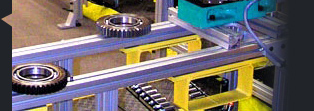
Proper Bearing Installation
When installing mounted bearings on a jack shaft arrangement, always align set screws (best at 12:00) before you torque them down. This will help compensate for shaft inaccuracies. Also, alternate tightening the set screws in the same manner as you would with the lug nuts on the wheel of a automobile (50% 100% 50%).
Source:  Sealmaster Advanced Bearing School
Saving Downtime
Always consider electronic overload protection for automation equipment, pumps, and conveyors. It is inexpensive, easy to install and provides continuous monitoring of load condition to avoid costly downtime.
Gearbox Selection
Keep in mind, when sizing a gearbox to consider using a Helical Bevel line of gearbox. They feature higher efficiency and torque ratings than a worm gear type of reducer. You maybe able to reduce the size of your gearbox by choosing a Helical Bevel.
Warner Electromodule Clutches & Brakes
One of the most frequently reported problems with electro module clutch-brake combinations is the brake works but the clutch does not (right out of the box).
About 99% of these problems are caused by overlooking or misunderstanding the instructions. Because of the nature of this design, only the brake armature & magnet can be pre gapped at the factory. When the combination clutch brake is assembled the user must set the gap of the clutch armature/rotor. The gap is easily set but the factory instructions can be difficult to understand.
- The rotor must be rotated until an oval slot is visible through the cooling slots in the outer clutch housing.
- Insert a flat blade screwdriver through the slot, between the clutch & brake armatures.
- Twist the screwdriver to force both armatures apart (away from each other).
- Rotate the output shaft of the brake 180 degrees and repeat the process.
This sets the gap and will be automatically maintained for the life of the unit.
How hot is too hot?
Often we receive calls from customers who believe a component just installed is running " TOO HOT ". More often than not it is running within operating temperature design limits. We usually have a limited means of perceiving temperature available. Our hand on average a temperature over 140 degrees Fahrenheit is too hot to touch. Most power transmission components are designed to operate up to 180-220 degrees Fahrenheit, when loaded to design capacity. If a component seems too hot, try to measure the actual temperature with a thermometer. If one is not available you can resort to the water test. Water boils at 212 degrees Fahrenheit. If a drop of water instantly boils when applied to the suspected component you can be sure it is over 212 degrees Fahrenheit. Note that does not always mean it is overheated as many components can operate at 220 degrees Fahrenheit without problems. If your water drop does not vigorously boil off, but just evaporates slowly, your temperature is less than 212 degrees Fahrenheit it is probably well within design limits. If in doubt give us a call.
Linear Positioning Accuracy
FAQ regarding positioning accuracy on linear systems involves the accuracy of the rotating to linear device. i.e. ball screw, acme screw, or belt.
Ball screws may give a lead accuracy of +/- .006 in. per ft.
Acme screw may give a lead accuracy of +/- .010 in. per ft.
Belts may give a repeatability of +/- .012 in.
In effect these tolerances represent the capability of the screw or belt only. It is important to remember that how you locate to your desired position will determine the systems accuracy. For example if a mechanical limit switch is used for home or at position you may get an accuracy of +/- .003 in. due to the switch. A small diameter proximity switch may give you +/- .001 in. Thus even though your screw or belt may inherently have only +/- .006 in. per ft. accuracy. Your system can give tighter results providing it is a point to point move.
Roller Chain Sprockets With Extended Pitch Chain
Can you use Standard Roller Chain Sprockets with Extended Pitch Chain? Page F-76 of Browning catalog 11 answers this question.
Standard Roller Chain Sprockets with less than 24 teeth will no run satisfactory with Extended Pitch Chain and should not be used.
Standard Roller Chain Sprockets with 24 to 30 teeth should be used as temporary replacements only. Standard Roller Chain Sprockets with more than 30 teeth will run satisfactory with Extended Pitch Chain with Standard Rollers in most cases.
Using Sprockets with an odd number of teeth will assure even wear on all teeth.
McGill Nomenclature
| PREFIX | EXPLANATION |
|---|---|
| CF | CAM FOLLOWER |
| -S | With LUBRI DISC seals (always added as a suffix) |
| CCF | CROWNED OD CAM FOLLOWER |
| -B | WITH HEX HOLE (always added as a suffix) |
| CFE | CAM FOLLOWER WITH ECCENTRIC STUD |
| CFH | CAM FOLLOWER WITH HEAVY STUD |
| CCHF | CAM FOLLOWER, CROWNED OD & HEAVY STUD |
| CYR | CAM YOKE ROLLER |
| CCYR | CAM YOKE ROLLER, CROWNED OD |
| BCF-S | BUSHING TYPE (non roller), WITH SEALS |
| BCYR-S | CAM FOLLOWER, W/O STUD, WITH SEALS (yoke type) |
| M | ANY NUMBER BEGINNING WITH "M" IS METRIC |
| PCF | PLAIN OD TRAKROL BEARING |
| VCF | V-GROOVE TRAKROL BEARING |
| UCF | U-GROOVE TRAKROL BEARING |
| FCF | FLANGED OD TRAKROL BEARING |
Part numbers are arrived at by combining elements from the above with the diameter of the unit.
For example:
CCFE-3-SB
Crowned OD Cam Follower (CCF)
Eccentric Stud (E)
3" Diameter
With Seals (S)
With Hex Hole (B)
CF-1-1/2-B
Cam Follower (CF)
1-1/2" Diameter
With Hex Hole (B)
VCF-6-1/2
V-Groove TRAKROL Bearing
6-1/2" Diameter
BCYR-2-1/2-S
Yoke type Cam Follower, No Stud (BCYR)
2-1/2" Diameter
With Seals (S)
Torque Overload Release Couplings
How to Avoid Damage to Driving & Driven Equipment and Minimize Downtime (Solution: Torque Overload Release Coupling)
Kop-Flex' Series H Shear Pin Cartridge couplings are one of the excellent options we have to offer. Kop-Flex Shear Pin Cartridge couplings are designed to physically disconnect the driving and driven equipment during torque overload. The purpose of the design is to protect the equipment - motor, gearbox, pump, roll, etc. - from damage due to torque overload.
How does it work?
The shear pins in the coupling shear at a predetermined design valve and physically separate the driving from the driven half of the coupling - basically the shear pins act as a mechanical fuse. The coupling halves separate the rotate on the sealed radial bearings of the shear cartridge without transmitting any torque at this point. The drive can then be shut off, the shear pins replaced in the field, and the operation restarted without disassembling the coupling or moving the driving or driven equipment - viola minimum downtime!
Advantages and Unique Features of Kop-Flex' Design
- Minimal downtime through quick start up after the shear pin breakage;
- Low cost of rebuilding the coupling after the shear pin breakage - only replace shear pins;
- Off the shelf availability for quick shipment - Series H coupling half as well as shear pin cartridge assembly;
- Hollow shear pin that can be accurately set to predetermine shear torque value;
- Sealed radial bearing - designed for continuous operation without the need to lubricate;
- Spring loaded bevel washer to prevent the pins from welding and transmitting torque after shear pin breakage.
The Series H shear pin cartridge is available in various design options and configurations as outlined below. Besides the Series H design, also available are the Fast's shear pin (type FSP) and breaking pin (type FBP)
Series HSP Shear Pin (Close Coupled Coupling Arrangement)Series H shear pin cartridge coupling - HSP _ is used in typical overload limit applications where the distance between shaft ends is close.
Series HSPS Shear Pin (Spacer Coupling Arrangement)
The spacer design is for unique applications that require
torque overload design but has shaft separations greater than
close coupled configurations.
The floating shaft design offers the unique advantage and ease of replaceability of the coupling without moving the equipment. The design can be customized for any shaft separation that an application may require. The rigid hubs are mounted on the driving/driven equipment and the flex halves on the center floating shaft with the shear cartridge.
For more information on the Torque Overload Release Couplings refer to Kop-Flex Mill Products Catalog (KMP-99) pages 89 through 99.
Source:  Kop-Flex Coupling Comment #201, Parthiv Amin - Mill Products Manager
The proper method of loading a Shaft Coupling
In order to assure the correct shaft alignment of both sides in a coupling application, each side of the coupling should be installed with the capscrews in the coupling individually tightened to a snug position, and then tightened to the proper recommended torque value with a torque wrench. Only after the first shaft is installed in its portion of the coupling should the same process be repeated for the second shaft. This sequence of installation will assure that the individual shafts are properly aligned with the coupling itself, and with each other. An improper installation may result in less than optimal concentricity value as measured by TIR, possibly causing component vibration and damage.
Source: Tech Tip from Collars & Couplings, Inc.
Sizing or Re-Sizing V-Belt Drives
V-Belt drives have always been an integral part of our business here at MPT Drives. With the increased use of VFD’s in the HVAC Industry, their popularity has waned slightly, but there are still thousands of V-belt drives in the field.
Many times, these drives need to be changed, sometimes by changing one of the sheaves, sometimes a complete new drive is required. That is where MPT Drives comes in. We are more than happy to help. To adequately advise you on the best option for you, we need the following information:
- Motor HP
- Required Fan RPM
- All information about the existing drives (Sheave diameters, belts size, shaft diameters)
- Is there a belt guard or belt tube in place?
- Is an increase in speed going to adversely affect your motor’s amp draw?
Whenever possible, we will try to reuse the existing equipment. Just changing one sheave and maybe a set of belts will decrease down time and reduce costs. There are times when you need to replace the whole drive. If that is the case, we will make up to ten selections and make a recommendation as to what we think may be right for you. To accomplish this, we use Browning Edge® software. This software is available either on CD or on the Web. Based on the information we enter, The Edge® program will make up to ten selections to try to fit the specifications. They are listed in order of cost, least expensive on up.
One word of caution to customers using the Edge® software on their own; although Emerson-EPT will stand behind any drive selected by their software, the least expensive drives are shown first. Although it may appear attractive to save money on the initial drive, proper installation and maintenance are critical to keeping the drive running properly. Sometimes the savings are quickly eaten up by the higher maintenance costs. As with any product, proper maintenance is essential to V-Belt drives, but it may be more cost effective to spend a little more on a less “finicky" drive. We will be happy to lend our guidance to help you make your selection.
Torque Limiters- Mechanical Vs. Electronic Devices
Most machines can be damaged by mechanical jams (overloads) Often a machine’s designers mistakenly believe that the heaters, called “overloads" in a motor starter, or the over-current protection in a variable speed drive, will protect the machine from mechanical overloads caused by jams. These devices are designed to protect against electrical overloads, they should be thought of as functioning as a fuse. They are not intended to function as a mechanical overload protection device.
The three main reasons that these devices cannot be relied on to provide mechanical overload protection are:
- Current based devices must be sized to accommodate startup current inrushes. Starting currents can be as high as 600 % of the full load current.
- Amperage (Current) change, is not linear with respect to actual motor load change, and usually will not reliably react fast enough to protect the driven equipment.
- Many of these devices are deliberately designed to be a time-delayed feature.
Mechanical drive components are better protected with the installation of a dedicated torque-limiting device. Some common mechanical torque limiting devices are: Shear Pins, Friction Clutches, and Ball-Detent Clutches. Mechanical Torque Limiting Devices have an advantage over Electronic Torque Limiters only in small sizes, when they are inexpensive by comparison to the electronic version. Mechanical devices have many disadvantages, regardless of their size. Many designs are difficult to reset. In a shear pin design, the old pin must be removed. The pin liners must then be aligned, and a new pin must be inserted. If a proper shear pin is not readily available, any pin of a similar size is often inserted in place of a proper shear pin. If this happens, all overload protection is obviously lost. In a Friction Clutch installation, when an overload setting is exceeded, the clutch will slip. These devices will quickly overheat, and wear out, if not detected soon by plant personnel. Each time a friction clutch slips, the overload setting is reduced by wear. Ball Detent Clutches need to have a proximity switch, or limit switch associated with them, to shut off the drive, when they are tripped by an overload. If this switch fails, or is out of position, the Ball Detent Clutch will quickly fail.
Most mechanical overload protection devices are located in the open, and are subject to “Adjustment" by the machine operators. Often this means that they are set to their maximum setting, which usually renders them useless, eliminating their function as a torque limiter.
Electronic overload protection devices are generally divided into two main categories, Current Monitors, and Power Monitors. Current Monitors are less sophisticated devices that measure the current draw of the drive motor. The main limitation of current-based devices is that changes in current, lag behind the changes in the actual load, as seen by the drive motor. This means that they are slower to react to an overload. The better electronic overload protection devices are Power Monitors. These devices look at both current and voltage, and apply a mathematical formula to determine the actual power produced by drive motor. Typically this measurement is done every eight milliseconds, as the sine wave crosses the zero point. These devices are far more accurate, and much faster reacting than current-based overload protection devices. Their performance far exceeds the performance of any mechanical overload device. Power Monitor load limits can be set in several important ways, an ultimate high limit, a rate of change limit, and for some applications, a low limit. A high limit can be used for gradual increases in load, a rate of change will detect sudden increases, such as are seen in a jam condition, and low limits are used in detecting conditions like dry pumps, or failed drive components. These limits are easily set; all you need to do is monitor the load seen by the running machine, and set the limits somewhat higher (Or lower) than the normal condition. You then need to observe the operation, to ensure that there are no nuisance trips. If nuisance trips occur, a gradual adjustment is needed, until the nuisance trips are eliminated. When any of these preset limits are exceeded, an output relay changes state. This is normally used to shut off the drive motor, and can be used to sound an alarm, light a warning etc.
Power monitor devices have many advantages over conventional mechanical torque limiting devices. They are less expensive than large mechanical torque limiters. Because they can be mounted in a locked enclosure, they are resistant to unauthorized “Adjustment" Many power monitors have output functions, that will output an analog signal that is relative to load. This can be recorded to catch changes in machine load, such as bearing condition, broken, or dull cutting tools, and many others. There are also models that can be monitored by computer.
Protection from mechanical jams should be designed into any machine that could be damaged from such an event. Power monitors are the best performing solution, and can be less expensive to install, and operate than many common mechanical overload devices. For more information on overload protection devices, contact your MPT Drives sales representative.
What is Horsepower? What is Torque?
There is a lot of discussion about horsepower and torque. I find most people don’t really have a clear understanding of exactly what each of these terms actually mean. We are usually exposed to these terms early in life, about the time we begin to get interested in cars. We read in automotive magazines dynomometer test reports, that a particular car produces X amount of horsepower and torque. I find that most people look at the horsepower numbers, but usually ignore the torque figures. I think that this is because people believe that they understand what horsepower is but that they have no clue as to what torque is. What most of us really know about horsepower and torque is that more is better; at least when it comes to our cars.
Horsepower is a measurement of kinetic energy, and torque is a measurement of force. Either one can be derived from the other with the appropriate formula.